TO Category:
Milling work
Devices for installing and fixing workpieces
Universal fixtures (tacks, corner plates, prisms, machine vise, etc.) are designed for fixing workpieces. They are mainly used in single and small-scale production.
Clamps are used to fasten workpieces of complex shape or large dimensions directly on the machine table. On fig. 1 shows various types of clamps: tile (Fig. a), fork-shaped (Fig. b), trough-shaped (Fig. c), curved universal. All clamps have oval holes or recesses for moving the clamp relative to the workpiece. On fig. 2, a shows the fixing of the workpiece on the machine table with a tile clamp, which rests on the workpiece at one end and on the lining with the other. The head of the bolt is inserted into a T-slot. table through the clamp hole. When tightening the nut with a wrench, the clamp is pressed against the workpiece, securing it. As a lining for clamps, stepped stands are used (Fig. 2, b), various bars of the required height, or special supports for tile clamps (Fig. 2, c).
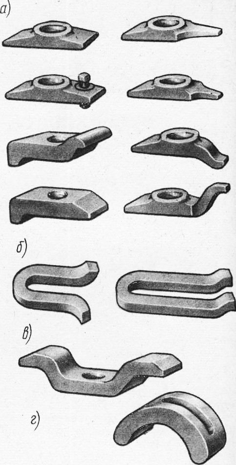
Rice. 1. Tacks
Workpieces of small dimensions in height can be fixed directly on the machine table with tacks (Fig. 20, d and e). In some cases, it is convenient to use a spring-loaded clamp with a sufficiently large range of adjustment for reach and fixing the workpiece with a handle. Very convenient to use is a height-adjustable curved universal clamp (Fig. 2, f).
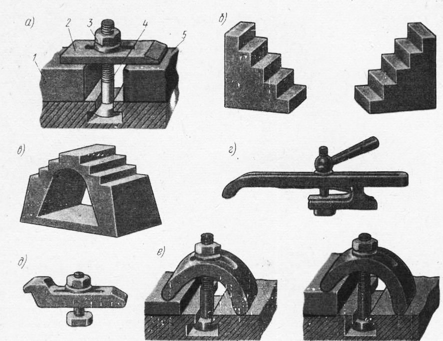
Rice. 2. Fixing the workpiece on the machine table
Workpieces of different heights can be fixed with universal clamps. In the clamp shown in Fig. 3, a, the workpiece is fastened with an L-shaped clamp with a recess in which the cracker is installed. The workpiece is fixed with a bolt and nut. The stepped clamp (Fig. 3, b) consists of a body in which there are ledges (steps) located along the recess of the body at different heights. A lining rests on the ledges, which enters the slot of the clamp with its slot, and is pressed against it by a spring. The clamp can be rotated 180°. The clamp body has a through threaded hole for the clamp bolt and for attaching the entire clamp to the T-slots of the machine. The clamp allows you to fix workpieces of different heights in a certain range.
When finishing milling, tightening the bolts should not cause deformation of the workpiece.
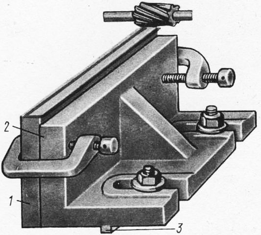
Corner plates are used to install and fasten workpieces having two planes located at an angle of 90 °. On fig. 5, a shows a conventional corner plate. It has one or two stiffeners and two shelves (equilateral or unequal, wide or narrow) located at an angle of 90 °. On fig. 5, b shows a rotary corner plate, the shelf of which can be rotated around the axis after releasing the nut and set to the desired angle on the scale. Such plates are used in the processing of inclined planes.
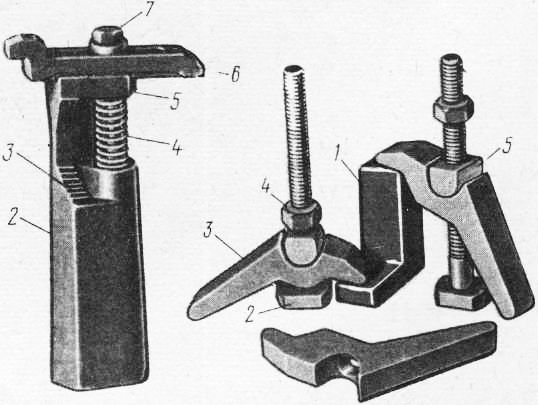
Rice. 4. Universal clamps
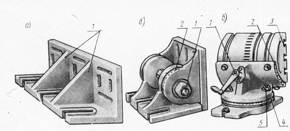
Rice. 5 Corner plates
On fig. 5, c shows a universal corner plate that allows rotation of the fixed workpiece in two planes: horizontal - with handle I and vertical - by turning the block fixed with bolts. The plate is a turntable with three T-slots. The angle of rotation of the table is counted on a scale.
On fig. 5 shows the fastening to the corner plate with clamps of a long and wide, but thin lath. For proper installation of the corner plate on the table, its base has a spike that fits into the groove of the table.
Before fixing the workpiece on the corner plate, it is necessary to carefully verify the correct installation of the plate itself on the machine table with a thickness gauge or indicator.
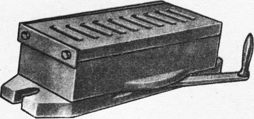
By design, machine vices are divided into simple, rotary and universal. On fig. 7 shows a machine vice with a manual clamp. They are a simplified modification of the pneumatic machine vice with a high degree of modification (80%). To power the hydraulic drive of machine hydraulic or pneumatic vices, an individual hydraulic station of the GMT type or a pneumohydraulic converter of the PMT type is used, operating from the factory pneumatic network. The use of special removable jaws and linings for machine vices leads to a significant reduction in the time spent on setting workpieces. On fig. 8 shows several examples of designs of replaceable jaws for fixing workpieces (a - with inclined planes; b - processed along the outer planes and ends; c, d - shafts). Similar sponges can be made if necessary for any processed workpieces.
Rice. 6. Fixing the workpiece on the corner plate
Rice. 7. Machine vice with manual (pneumatic) clamping
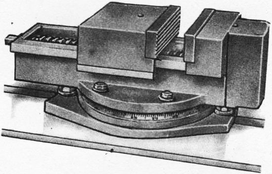
Hydraulic and pneumohydraulic vises provide more clamping force than pneumatic vises. On fig. 26 shows a hydraulic swivel vice, which features the simultaneous movement of both jaws, providing self-centering of the workpiece. The workpieces are fixed under oil pressure of 4900 kPa coming from the hydraulic system of the machine or from a separate pumping unit into the base cavity. Under oil pressure, the piston moves down, and the levers, turning around their axes on the screws, squeeze out both sponges at equal distances. T-slots are provided on the upper and side planes of the jaws for installation and fixing of workpieces or special overlays. Preliminary adjustment of the vise is made with screws. The ability to rotate the body relative to the base 9 allows processing workpieces with a rotation around the axis within 360° with an accuracy of 1° on the scale. The mechanized stroke of the movable jaws in this vice is 24 mm. When adjusting the jaws are bred from 0 to 200 mm. The clamping force at the specified oil pressure reaches 53955 N.
Recently, fixtures with barium oxide magnets have begun to be used for fixing steel and cast iron workpieces with a flat supporting surface. Devices with barium oxide magnets have a number of advantages compared to previously used magnetic devices, namely: there is no residual magnetism in the fixed workpieces, the metal-cutting tool is not magnetized, non-deficient materials are used for the manufacture of such devices.
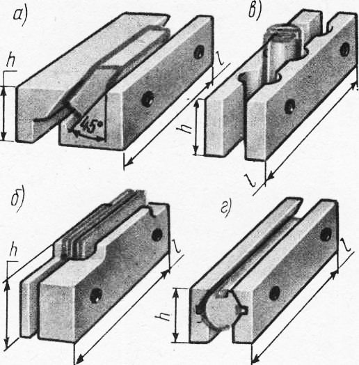
Rice. 8. Replacement jaws for machine vise
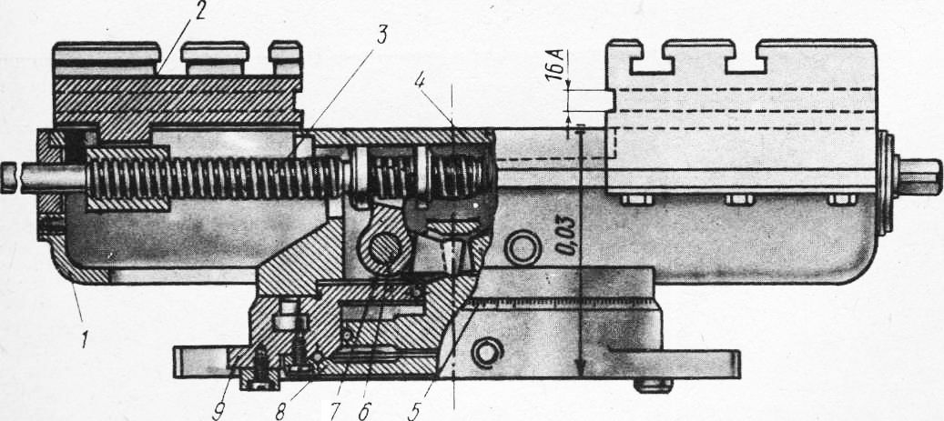
Rice. 9. Hydraulic self-centering swivel vise
Rice. 10. Device with barium oxide magnets
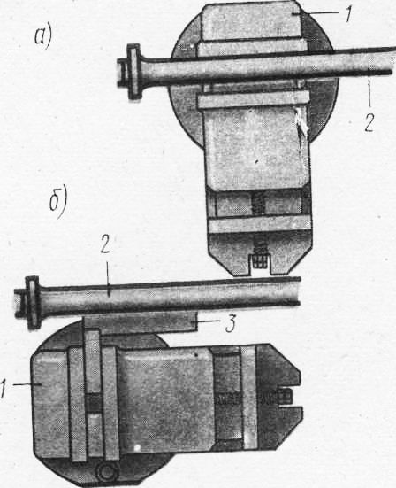
Rice. 11. Installing the vise on the table of the milling machine
Magnetic vices can be installed using dowels (crackers) inserted into the groove of the vise base. These dowels are inserted into the middle groove of the machine table. Screwing the nuts of the clamping bolts is done gradually. Tightening one nut too hard and then all the others can cause the vise to skew. The installation of the vise can be carried out directly on the milling mandrel. The jaws of the vise are set parallel to the axis of the milling mandrel. In this case, the mandrel is brought into contact with the fixed jaw of the vise and then the nuts of the hold-down bolts are tightened. On fig. 11, b shows the installation of a vice for the case when the jaws are located perpendicular to the axis of the milling mandrel. In the vise jaws, a square is fixed, which is pressed against the milling mandrel with a free shelf. To avoid deformation of the mandrel, it is necessary to use a feeler gauge, which is inserted between the milling mandrel and the fixed jaw or free flange of the square. When properly installed, the probe can be pulled out with little effort.
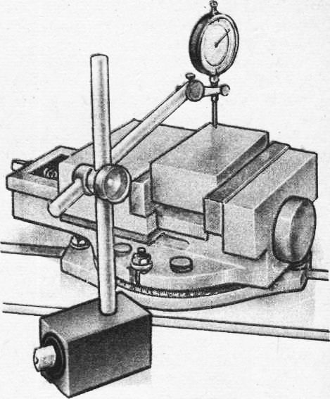
Rice. 12. Alignment of the workpiece when it is installed in a vice
Alignment of workpieces processed in a vice. Simultaneously with fixing the workpiece to be processed, the correctness of its position and the correction of installation errors are checked. The correctness of the installation of the workpiece in the vice in relation to the machine table is checked by a thickness gauge. For a more accurate installation of the workpiece, instead of a thickness gauge, an indicator with a stand is used.
When using various removable linings for the vise, the process of installing the workpiece is simplified and, in some cases, subsequent alignment is not required. A tight fit of the lower plane of the workpiece to the lining is achieved by tapping with a copper or brass hammer. Before clamping workpieces with already machined surfaces in a vice, it is imperative to remove the burrs formed during the previous transition, if they could interfere with the correct installation or clamping of the workpiece. The jaws of the vise should be covered with pads made of sheet copper, brass or aluminum to protect the machined surfaces from dents. In addition, it is always necessary to sweep away chips from the table, the supporting surfaces of the workpiece, clamping devices, vices, and linings before processing. Thin-walled workpieces of low rigidity should not be clamped with great force in order to avoid their deformation, and, consequently, distortion of dimensions and shape after processing.
In large-scale and mass production, special devices for installing and fixing a specific part are widely used. Fixing workpieces in special fixtures not only reduces the time for their installation and alignment, but also ensures higher processing accuracy. The pneumatic system must be checked in operation for air leakage. The same must be done for the hydraulic clamps.