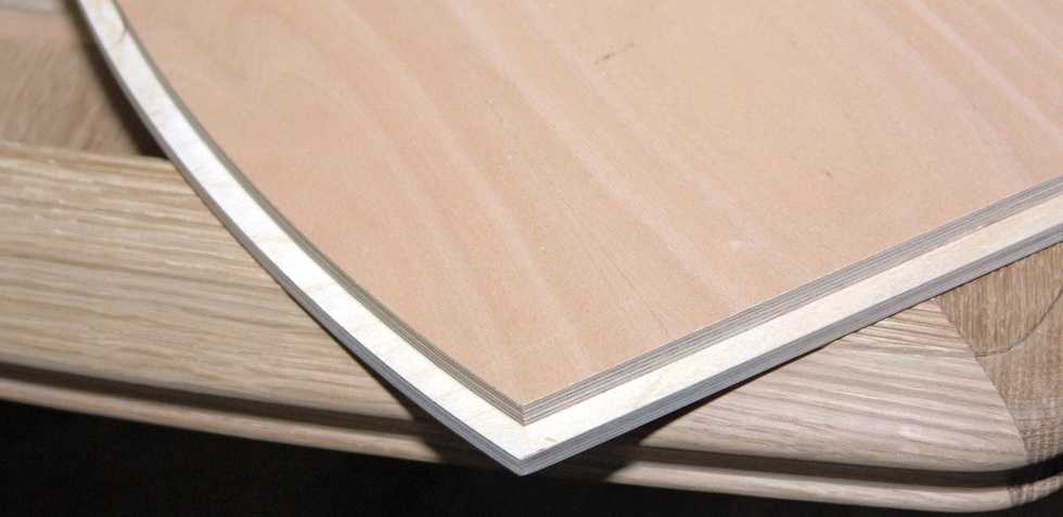
Knowing how to make a tenon groove with a manual router, you can even make at home not only beautiful, but also reliable furniture, but also various wood structures, characterized by excellent bearing capacity. According to the "thorn-groove" system, not only elements of various furniture (tables, chairs and shelves) are connected, but also the frames of low-rise buildings that experience significant loads during operation.
In order to make a spike on a wooden beam with a manual milling cutter, several conditions must be met:
- securely fix the workpiece and correctly orient it in relation to the guide sole of the router;
- set the height of the working part of the cutter so that the tool removes a layer of material of the required thickness from the surface of the workpiece being processed.
Even using the simplest tenoning device for a milling cutter when performing such processing, you can not only increase its productivity and quality of the result, but also make the process safer. It is especially important to use such a device, which can be made with your own hands, in cases where the furniture is produced not in single copies, but in series (in this case, the master has to perform a large number of such operations both with the same type and with wooden furniture of various shapes and sizes). details).

Tools Used
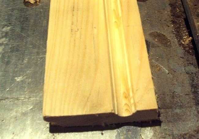
The creation of spikes and grooves, with the help of which the connection of two wooden blanks will be ensured, assumes that a sample of the material is made on the side surface of the beam or board with a manual milling cutter. In this case, all geometric parameters of the elements of the future connection must be strictly observed.
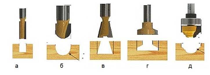
To perform this operation with a hand router, you can use tools with shank diameters of both 8 and 12 mm. The most versatile in this case is the groove cutter, the cutting part of which works as follows:
- the side surface forms the walls of the groove and the sides of the tenon;
- the end side processes the bottom of the groove and removes a layer of material of the required thickness from the base of the spike.

Thus, using a tool of this type, it is possible to form both a tenon and a groove on the side surface of a beam or board. At the same time, their sizes can be adjusted within a fairly wide range.
In cases where higher requirements are placed on the reliability of the connection of wooden parts, the grooves and spikes are made not of a rectangular shape, but of a shape called the “dovetail”. Grooves and spikes of this configuration are created using dovetail cutters. It is also possible to perform the procedure for forming grooves and spikes of this shape with a hand mill, but for these purposes, devices of a different design should be used.

Dovetail sampling using a template
So that the question of how to make a groove in a board and a beam or a spike on their side surface does not cause any particular difficulties, it is better to use a power tool equipped with comfortable side handles, a wide guide sole and the option of protecting the spindle from turning during the replacement of the cutter. In addition, it is desirable that such equipment has a side stop, due to which the overhang of the cutter used with it in the kit will always remain constant.
How to make a stud picker
When forming spikes on wooden blanks with a manual milling cutter, it is not fixed in space in any way and is brought to the workpiece manually. That is why it is very important that when using a power tool, the workpiece is in a fixture that can ensure not only its secure fixation, but also the accuracy of the spikes formed on its surface.
The design of the simplest device that is able to cope with such tasks is:
- several fixed guides (lower, upper, side);
- movable bar, due to which you can adjust the length of the sample.

Such a device is manufactured, the dimensions of the components of which are selected individually, in the following sequence:
- Along the edges of the plywood sheet, side vertical elements of the same height are fixed, in the central part of which cutouts are made.
- Guides are installed on the side elements, along which the sole of the hand mill will move.
- To limit the travel of the hand router along the upper rails, the side rails should be fixed on them.
- On a sheet of plywood, which plays the role of the base of the device, it is necessary to install a movable element, with which the amount of overhang of the edge of the workpiece to be processed will be adjusted. For fixing, you can use a regular thumb screw or any other suitable fastener.
In the manufacture of the device of the proposed design, the following points should be taken into account:
- The height of the top guides should be the sum of the thickness of the workpiece and the amount of small clearance required to install the fixing wedge.
- The cutouts in the side vertical elements are made so wide that it takes into account the length of the spike being formed.

It is possible to work with the device of the proposed design with a manual milling cutter of almost any modern model, the options of which provide for the possibility of adjusting the cutting speed, the amount of feed and overhang of the working part of the tool used.
To create a dovetail spike on the side surface of a beam or board, a device manufactured as follows is used.
- A hole is made in a sheet of plywood, from which the cutting part of the dovetail cutter will protrude.
- A manual router is fixed from the bottom of the prepared plywood sheet. To do this, you can use clamps, screws or any other fasteners.
- On the surface of the plywood sheet, along which the workpiece will move, a board 2.5 cm thick is fixed. It will act as a guide element. Such a board is a consumable and is used once with a cutter of a certain diameter.

Such a device can be installed between two chairs or used to place it in a more convenient and reliable design.
Creating spikes on bars and boards
Using wood splicing cutters for a hand router and the above fixture, processing is performed in the following sequence.
- The part to be machined is placed on the lower reference plane.
- The edge of the part on which the spike will be formed is placed in the cutout of the upper guides and moves in it until it stops against the movable element of the fixture.
- The movable element is fixed in the desired position.
- Using a wedge element, the upper plane of the part is pressed against the upper guides.
- A manual router is placed on the upper guides.
- The tree, using a tool installed on the router, is first removed from one side of the spike being formed.
- After processing one side, the workpiece is turned over and the formation of the second side of the spike is performed.

Even such a device, simple in design, makes it possible to process tenon-groove joints with high precision and productivity using hand mills.
Before starting work, such a device must be configured. This can be done using the following algorithm.
- The tool installed in the hand router is lowered until it comes into contact with the surface of the base plywood.
- The thickness of the part is measured.
- The thickness of the workpiece is divided by 4. The result will be the distance by which it is necessary to raise the cutter above the base surface.

Using the dovetail pattern, grooves and spikes are created at half their thickness, which is explained by the peculiarities of this type of connection. To make a groove in a beam and a board, as well as to form a dovetail spike, the device must also be adjusted and its components fixed in the desired position.
In the presence of a milling machine, work on inserting loops, forming complex holes, recesses, woodcarving, etc. is really simplified. But this does not mean at all that it is necessary to have professional and expensive equipment: it is enough to have a simple manual device.
The only thing you need is to be able to handle wood and use power tools. In addition, you need to have a desire, otherwise there will never be a result without it. Those who have no desire to work simply buy furniture or hire craftsmen to, for example, install a new door and embed locks. Any work, especially with a power tool, requires certain knowledge, and especially safety precautions.

The milling device is intended for processing both wood and metal. With its help, it is possible to form recesses or holes of any configuration. This greatly simplifies tasks such as tapping hinges and tapping locks. To do this with a chisel and an electric drill is not so easy, and it takes a lot of time.
There are stationary milling devices and portable (manual). Manual electric cutters are considered universal devices, with the help of which, in the presence of nozzles, it is possible to perform operations for various purposes, it is enough just to change the position of the part relative to the device or vice versa.
Stationary devices are used in factories or factories where mass production of wood or metal products is established. Under such conditions, the cutting nozzle is stationary, and the workpiece moves along the desired path. When using a hand tool, on the contrary, the part is fixed motionless and only then it is processed, although there are parts that require fixing a hand tool. This is provided for in the design, therefore, it is considered more universal. This is especially true when you need to process a large number of parts, and it is not possible to use a stationary machine.
 Homemade milling machine - a horizontal platform with a hole in the center, from below to which a manual fixture is attached.
 There are many types of milling machines, but for use at home or for starting a business, universal models are more suitable. As a rule, they are equipped with a set of cutters and various devices for performing various kinds of operations. The only thing is that with a manual router, simple operations can take much more time than with a stationary machine.
With the manual milling device it is possible to:
- Make grooves or recesses of arbitrary shape (curly, rectangular, combined).
- Drill through and non-through holes.
- Process ends and edges of any configuration.
- Cut out complex shapes.
- Carry out drawings or patterns on the surface of parts.
- Make a copy of the details, if necessary.
 Copying parts is one of the functions of any electric milling machine.
 The presence of such functions makes it possible to simplify the production of the same type of furniture or the production of identical parts that are not related to the production of furniture. This is one of the main advantages of this tool. As a rule, for the production of the same type of parts, it is necessary to install copy machines that are designed to perform only one operation, which is not always profitable, especially in small enterprises.
Getting Started and Caring for the Tool
To understand how this device works, you should familiarize yourself with its main parts and their purpose.
Composition and purpose of the main nodes
The manual milling fixture consists of a metal case and a motor, which is located in the same case. A shaft protrudes from the body, on which various collets are put on, serving as adapters. They allow you to install cutters of various sizes. A cutter is inserted directly into the collet, which is fixed with a special bolt or button, which is provided on some models.
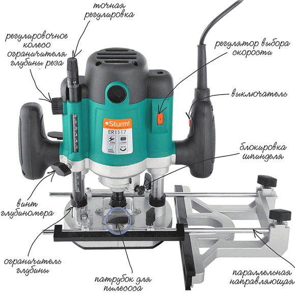 The main elements of a manual milling device and their purpose.
 The design of the milling fixture provides a metal platform, which has a rigid connection with the body. It is attached to the body with two rods. From outside the plate has the smooth covering providing smoothness of the movement in the course of work.
The manual milling fixture has some characteristics that can be adjusted:
- Due to the handle and scale setting the depth of milling. Adjustment is carried out in increments of 1/10 mm.
- By adjusting the speed of rotation of the cutter.
At the initial stages, when the tool is mastered, it is better to try to work at low or medium speeds. Although you should always remember that the higher the speed, the better the work. Especially when it comes to responsible, visible areas that cannot be masked.
In addition to these levers, there is also a button for turning the product on and off, as well as a lock button. These elements are considered the main ones that ensure the quality and safety of work. There is also a parallel stop, which contributes to ease of use. It can be rigidly fixed or with the ability to adjust the shift of the working area, in the direction from the center.
Caring for your handheld router

Usually, a factory product falls into the hands of a person tested and lubricated, so no additional measures should be taken. Only in the process of its operation it is necessary to monitor its cleanliness and serviceability. At the same time, it should be regularly cleaned of dust and change the lubricant, if the passport says so. Especially lubrication is needed for moving parts. Alternatively, you can use aerosol lubricants, but you can get by with the usual ones, such as Litol. The use of thick lubricants is not recommended, as chips and dust stick to them. If aerosol lubricants are used, then this factor can be eliminated.
Lubrication also requires a sole - a smooth part of the body. Regular lubrication will ensure the desired smoothness of movement.
Despite this, the purchased item should definitely be checked for build quality and the presence of lubrication.
Unfortunately, not all manufacturers, and especially domestic ones, care about build quality. There are cases when, after the first hours of operation, screws or screws are unscrewed from the product, as they were not tightened properly.
Rotation speed adjustment
The operation of any tool is associated with certain conditions related, first of all, to the nature of the material being processed. It can be plywood, composite material or regular wood. Depending on this, the rotation speed on the electrical appliance is set. As a rule, the technical data sheet always indicates the operating parameters of the device, depending on the technical characteristics and characteristics of the surfaces being processed, as well as the cutters used.
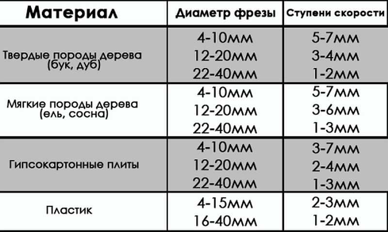 Processing speed indicators when using various cutters.
 Cutter fixation
The first thing the work begins with is the installation and fixing of the cutter. At the same time, one should adhere to the basic rule - all work is carried out with the cord removed from the outlet.
The cutter is set according to certain marks, and if they are absent, then to a depth not less than ¾ of the length of the cutter itself. How to install the cutter on a specific model, you can learn from the instructions, which must be present in the technical documents for the device. The fact is that each model can have its own design features and it is not possible to talk about this in the article.
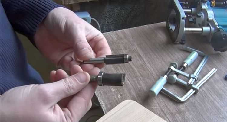
 Installing the cutter on the device before starting work.
 There are models both simple and more "advanced", as they say. Some models have a shaft rotation lock button, which makes it easier to install the cutter. Some, especially expensive models, are equipped with ratchets. So it’s impossible to describe specifically the process of installing the cutter, and it doesn’t make sense, since everyone who is familiar with the operation of such devices will figure it out at the moment.
Milling depth adjustment
Each model has its own maximum cutting depth. At the same time, it is not always the maximum depth that is required, but a certain depth, which is set before work. Even if the maximum depth is required, then, in order not to overload the device, the milling process is divided into several stages, changing the milling depth in steps. For adjustment, special stops are provided - limiters. Structurally, they are made in the form of a disk located under the bar, on which stops of various lengths are fixed. The number of such legs can be from three to seven, and this does not mean that the more of them, the better. It is better if it is possible to adjust each of the legs, even if their number is minimal. To fix this stop in the optimal position, you should use the lock, in the form of a flag.
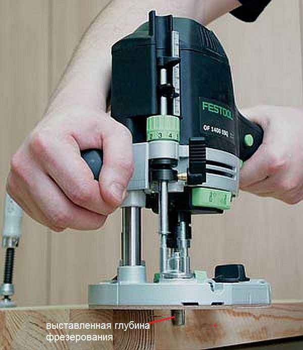
The milling depth adjustment process is as follows:

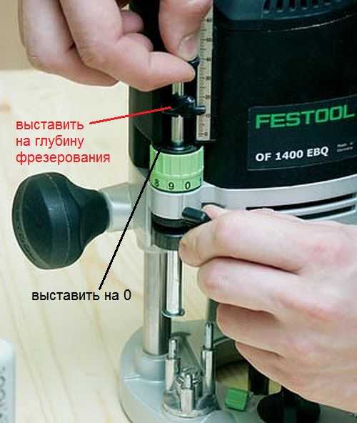 Thus, the workpiece is milled to a predetermined depth.
 On high-quality expensive models, there is a wheel for fine-tuning the depth of milling.
 With this wheel, you can more accurately set the depth without violating the previous setting.
 This wheel (green in the photo above) allows you to adjust the depth in a small way.
Cutters for manual milling tools

A milling cutter is a cutting tool that can have an intricately shaped cutting edge. As a rule, all cutters are designed for rotational movements, therefore they have a cylindrical shape. The shank of the cutter, which is clamped in the collet, has the same shape. Some cutters are equipped with a thrust roller, so that the distance between the cutting surface and the workpiece remains constant.
Milling cutters are made only from high-quality metals and their alloys. If you want to process soft woods, then HSS cutters will fit, and if you need to process hard wood, then it is better to use cutters from harder HM grades.
Each cutter has its own technical characteristics, which provide it with high-quality and long work. The main indicator is the maximum speed of its rotation, which should never be overestimated, otherwise its breakdown is inevitable. If the cutter is dull, then you should not try to sharpen it yourself. Sharpening of cutters is carried out on special, expensive equipment. After all, it is necessary not only to sharpen the cutter, but also to maintain its shape, which is no less important. Therefore, if the cutter, for some reason, has become dull, then it will be cheaper to buy a new one.
The most popular cutters
There are cutters that are used in the work more often than others. For example:

 Groove molds are designed to create recesses in an arbitrary place on the workpiece.
 There are simple cutters, monolithic, made from a single piece of metal, and there are type-setting. Type-setting cutters consist of a shank, which serves as the basis for a set of cutting elements. By selecting cutting planes and installing them on the shank, using washers of various thicknesses, it is possible to form an arbitrary relief on the surface of the workpiece.
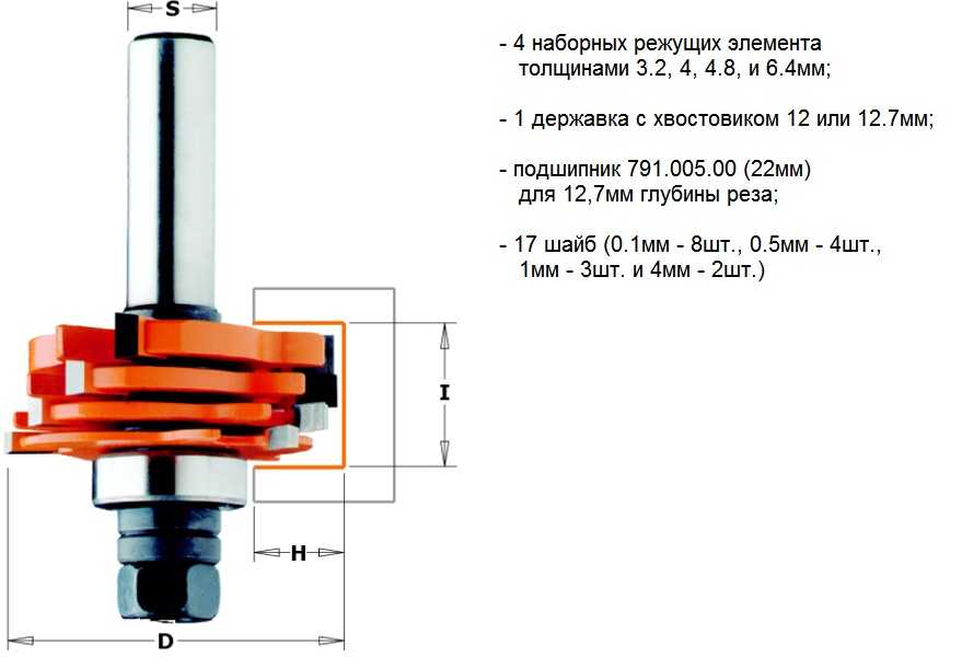 A type-setting cutter is a set of cutting surfaces and washers, which allows you to assemble the cutter of the desired shape.
 In fact, there are a lot of cutters and this is only a small fraction of what is produced. All cutters differ in shank diameter, cutting surface diameter, cutting height, knife position, etc. As for manual milling equipment, it is enough to have a set of five most popular milling cutters. If necessary, they can be purchased at any time.
Rules for working with manual milling tools
Working with power tools requires special rules, especially when there are rapidly rotating elements. In addition, as a result of the work, chips are formed, which scatter in all directions. Despite the fact that most models are equipped with a protective shield, this does not fully protect against the flow of chips. Therefore, it is better to work with such a tool in protective glasses.
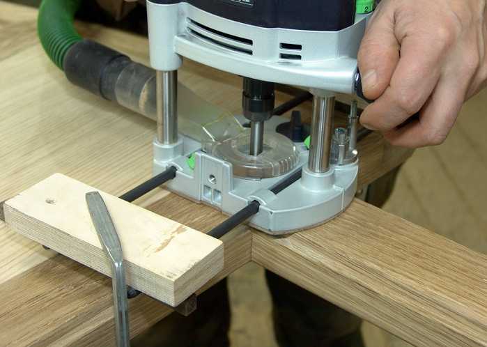 The photo shows a model where a vacuum cleaner is connected to remove chips.
 General requirements
If you fulfill the basic requirements for safe work with an electric hand router, then the end result will please you with the quality of work and a safe outcome. Here are the conditions:

The requirements are not very difficult and quite feasible, and ignoring them means putting yourself in danger. And one more thing, no less important, is the ability to hold a milling tool in your hands and feel how it works. If serious vibrations are felt, then you need to stop and analyze the reasons. It is possible that the cutter is dull or a knot is caught. Sometimes it is necessary to correctly set the speed of rotation of the cutter. Here you can experiment: either add speed or reduce it.
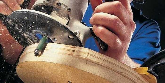
Edge Processing: Using Templates
Processing the edge of a wooden board is best done on a thickness gauge. If this is not possible, then you can use a manual router, although this will take some time. These works are carried out both without a template and with a template. If there are no skills or there are very few of them, then it is better to use a template. For processing edges, straight edge cutters are used, both with one bearing at the end of the cutting part, and with a bearing at the beginning (see photo).
 Edge cutters.
 For the template, you can take an already processed board or another, even object. Moreover, the length of the template must be greater than the length of the workpiece, both at the beginning and at the end of the workpiece being processed. This will avoid unevenness at the beginning of the edge and at its end. The most important thing here is that the template or object acting as a template has a smooth and even surface. In addition, its thickness should not be greater than the gap between the bearing and the cutting part.
The width of the part is less than the length of the cutting part
At the same time, the longer the cutting part, the more difficult it is to work with the tool, since more effort is required. In this regard, it is better to start work with cutters that have an average length of the cutting part. The working principle for edge processing is as follows:
- The template is attached so that it is at the desired height and has a flat horizontal surface.
- The template is firmly mounted to a table or other surface.
- The cutter with a roller is installed so that the roller moves along the template, and the cutter (cutting part) along the workpiece. To do this, perform all the necessary manipulations with the template, workpiece and tool.
- The cutter is set in working position and clamped.
- After that, the tool turns on and moves along the template. In this case, it is necessary to determine the speed of movement, which is determined by the depth of processing.
- The milling unit can be both pushed and pulled: as it is convenient for anyone.
After the first pass, you should stop and evaluate the quality of work. If necessary, another pass can be made by adjusting the position of the tool. If the quality is satisfactory, then the clamps are removed, freeing the workpiece.
With this approach, it is possible to remove a quarter along the edge or in some of its parts. This is done by setting the cutting edge so that it goes to the required depth into the part.
 A quarter taken on a furniture facade.
 If you replace the cutter with a figured one and shift the guide, as well as use the stop, you can actually apply a longitudinal pattern to the part (in the photo below).
 Drawing a longitudinal figured pattern on the workpiece.
 If you use a similar milling technique (with a template), then you can easily master the technique of working with wood in general. After some time, you can abandon the templates, as their installation takes a lot of useful time.
 How to make a smooth edge without a template: experience is indispensable here.
 The width of the part is greater than the length of the cutting part
Quite often, the thickness of the workpiece is greater than the length of the cutting part of the cutter. In this case, proceed as follows:
- After the first pass, the template is removed and another pass is made. In this case, the already processed part will serve as a template. To do this, the bearing is guided over the machined surface. If the cutting part was again not enough, then you will have to make another pass.
- For final processing, you should take a cutter with a bearing at the end, and the workpiece must be turned upside down, after which it is fixed with clamps. As a result, the bearing will move over the machined surface. This approach allows processing thick parts.
 The bearing is guided over the machined surface while the cutting edge machine the rest of the workpiece.
 In order to master the work of a manual milling tool, you will need a lot of rough workpieces, which you do not mind throwing away later. Nobody got it right the first time. For something to work out, you need to train hard.
Obtaining various curly edges
If a curly edge is required, which is most likely to be necessary, then first pay attention to the condition of this edge. If it is uneven, then it will have to be leveled and only then proceed to the formation of a curly edge, choosing the appropriate cutter.
 Rounded edge.
 It is necessary to prepare the surface so that the cutter does not copy the curvature along which the roller will move. In this case, a sequence of actions is needed, otherwise a positive result will not work.
If you want to process a frankly curved surface, then you can’t do without a template. It can be cut out of plywood, about 10 mm thick, having previously applied a drawing and sawed out the template with an electric jigsaw. The edge of the template must be brought to an ideal state with a manual router.
Milling - cutting of metals and non-metal materials, in which the cutting tool - milling cutter - has a rotational motion, and the workpiece is translational.
It is used for processing planes, curved surfaces of parts, threaded surfaces, teeth of gears and worm wheels, etc.
It is carried out on milling machines.
This definition is given by the Polytechnic Dictionary (Moscow, "Soviet Encyclopedia", 1989). It clearly requires additions, because the possibility of milling with a hand power tool is not mentioned at all. It is to her that our article is devoted.
Let's start with the fact that manual routers are different: edge, rod, rodless and simply specialized, for example, for cutting door locks or repairing window frames. Let us dwell in detail on the most versatile and, as a result, the most popular - rod.
Such a tool consists of two parts: the upper one, which includes the motor, handles, collet clamp, vertical position clamps, and the lower one - with rods, support sole and turret stop. Machines of this variety are distinguished by the fact that they allow you to dive into the material being processed to the required (within the limits of possibilities) depth.
Using examples of specific operations, we will consider important design features of modern devices of this type.
Getting ready for work
Let's start with the basics - preparation for work. Depending on the material and the task, a cutter is selected. For soft woods, plywood, MDF and aluminum, a nozzle with high-speed steel (HSS) knives is used, and more expensive, accurate and resistant, with carbide blades (HM) is not forbidden.
In other cases - chipboard, hardwood, composite compositions such as artificial marble and the like - the use of NM is mandatory. As already mentioned, one of the important features of carbide blades is precision: they leave a cleaner surface.
Depending on the diameter of the cutter and the material, the speed is set. Since the adjusting wheel is usually marked in arbitrary units, you will have to use the instructions, which indicate when what needs to be set. Generally speaking, setting the speed is a very responsible procedure.
Firstly, a large-diameter rig may not withstand too high a speed, and secondly, it is important to choose the right mode. With an overestimated frequency, there is a risk of “burning” the workpiece, with an underestimated one, productivity drops and the quality of processing deteriorates.
Having decided on the speed and type of cutter, install the equipment. The risks on the shank will help to do this correctly - you need to focus on them. If you need to deviate from the prescription (or it simply didn’t turn out), they use a simple rule - they fix 2/3-3/4 of the total length of the shank.
When buying a "consumable", it is important to remember that the clamp diameters are different. Usually there are collets for a shank of 6, 8 or 12 mm. If you don’t find the right size tooling, you shouldn’t be sad - just change the collet. It is an insert located inside the hollow drive shaft and fixed with a nut.
So, it's time to clamp the cutter. Do this with an open-end wrench, after securing the shaft. In simpler models, you will need a second key, in mid-level tools there is a stop button, but the most convenient latch is also equipped with a “ratchet” - in this case, you don’t even have to intercept it.

The cutter is clamped into the collet using an open-end wrench and a shaft lock mechanism. If the latter is not provided, you will need a second key. In this case, the installation is utterly simplified - the stopper is equipped with a switchable (unscrewing / screwing) "ratchet". The cutter is clamped, guided by the markings on it or based on the general rule (2/3-3/4 shank length).

The “head” of the tool is lowered to the stop with a cutter into the surface, after which it is convenient to fix it. Further, based on the overhang of the cutting tool and the desired depth of processing, choose the lowest of the suitable "legs" of the turret. This allows you to pass the workpiece in several stages, without repeating fine adjustments.
Often the position of each "leg" can be adjusted within a small range. A support rod is lowered onto the selected “stand”, having previously released its clamp. Without fixing it, but only pressing it with a finger, move the movable pointer along it, achieving its coincidence with the zero of the measuring ruler.

The bar is lifted until the pointer coincides with the required division of the measuring scale and clamped with a clamp.

If the operation requires precision, a good router will allow you to adjust the depth setting. It is changed without weakening (so as not to knock down) the fixation of the support rod, but by rotating the adjusting wheel. This can be done in advance, having achieved an exact match between the marks of the pointer and the scale, or after a trial pass.

When lowering the “head”, the cutter will enter the workpiece to the depth set on the calibrated scale.
Milling depth
The next step in the setup is setting the dive depth. It is set by a vertical stop, which can have several levels of adjustment. The most running is the position of the stop itself. Having rested it on the lowest of the legs of the “revolver” (if possible), loosen the stop latches (usually a wing clamp is implemented) and the “head” itself and lower it until the cutter touches the surface.
Note that it is not at all necessary to use a workpiece, it is better to perform this operation on the plane of the workbench, without the risk of damaging the part.
Now you need to fix the movable stop or just hold it with one hand, and with the other set the movable pointer (it “rides” up and down) opposite the zero division of the measuring scale, thereby calibrating the ruler. That's it, she's ready to go.
By moving the stop and following the pointer, adjust the depth and tighten the screw of the movable stop. If the router is “from simple”, then the adjustment is completed. Otherwise, the immersion depth is adjusted more accurately. The position of the movable (already fixed) stop is changed with an accuracy of tenths of a millimeter by turning the adjusting wheel.
It has latches ("snaps" in divisions) or simply rotates tightly. The first option is better, since the installation will not go astray during operation. It is good when such adjustment is implemented within a wide range, and it is very convenient when it can be done directly during operation.
Milling
Without going into the specifics of operations and skipping the item “Positioning the machine on a plane”, we will tell you how to get started. Having set the maximum immersion depth, it is, if necessary, “broken” into several steps - this is the purpose of the turret stop. In the vast majority of cases, it has three adjustable legs.
Sometimes there are more of them, for example, eight, which, however, is not considered a sign of a high-class instrument, but rather speaks of originality. Without touching the leg on which the immersion depth was set, the steps are set higher. The logic of actions here is the same as in the case of revolutions - too large a passage cross section at once will lead to slow movement and “burning” of the material, too small - to a loss of productivity.
The optimum is important. By turning the drum and moving from high to low stop, they move along the workpiece to the desired depth.
Starting each pass, act like this. Turn on the motor, lower the cutter (into the material or outside the workpiece, depending on the situation) and fix the “head” with a stopper. If there are several passes or there is no certainty that the operation was successful, it is repeated. It is important to remember that you need to move along the workpiece in a strictly defined direction - the material is towards the rotating knives.
It is impossible to drive the router “back to front”, as this will lead to a marriage. The direction of movement is usually indicated by an arrow on the sole; it is the same for all models.
A few words about the rod mechanism for raising / lowering the “head”. It is important to pay attention to the class of manufacture. Movement should be smooth and easy, without distortions and backlashes. It is good when the stopper acts on two rods - with this arrangement, the rigidity and accuracy of fixation are higher.
We hope that the reader has already understood that the main thing in the router is adjustment. They are required to ensure accuracy (this, by the way, largely depends on the rigidity of the structural elements) and convenience. But if you delve into the intricacies of performing operations, it becomes clear that another thing is no less important - the system.
It means a manual machine with devices for positioning it on a plane (without the latter, a milling cutter will be of little use, at least versatility will suffer greatly). Let's start the story about the "milling cutter + guide vane" system with the simplest cases.
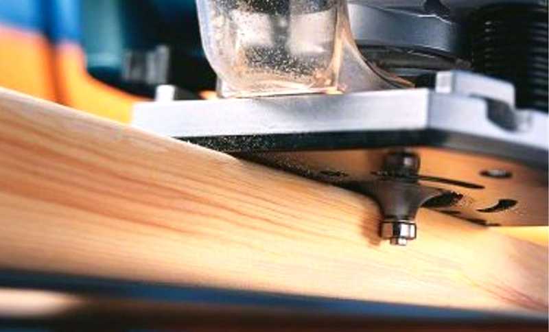
Cutter with support bearing
The cutter itself becomes the most elementary and compact device that sets the position of the machine, if it is supplemented with a miniature ball bearing. It is located under or above the cutting blades and respectively rests on the upper or lower edge of the edge. With the help of such equipment, shaped edges are obtained or grooves are cut for connection, edging, sealant, etc.
The advantages of the method include the ease of preparatory operations (only the vertical position needs to be adjusted) and the possibility of precise processing of rounded and curved edges (a typical example is a countertop). Disadvantages follow from merits - it will not be possible to make the curve even.
Parallel stop
All of the above is within the power of a conventional cutter without a support bearing (it is cheaper) if you use a copy ring or a parallel stop. Let's start with emphasis. They are equipped with all, without exception, milling cutters, but this does not mean that it is the same for everyone. In the simplest case, the stop is a bent metal plate on two steel rods with a cutout in the center.
In the sole of the milling cutter, guides with locks are provided for them. To ensure rigidity, they are made long (in the entire plate) or short, but double - for each rod, two spaced apart. Fixation occurs at a minimum of two points (one on each side), a maximum of four.
In the “primitive” version, such an emphasis has significant drawbacks - low rigidity of the stamped structure, difficulty in fine-tuning the position, restrictions on the diameter of the cutter used (it must fit in the central cutout), and the inability to adjust the base of the supporting surface. As it becomes more complex, the accessory gets rid of these shortcomings. For example, consider the most interesting construction, omitting the intermediate ones.
The bars are fixed in the sole not with separate clamps, but with one, acting on two sides at once - it’s more convenient. After the “pins” are clamped, the position of the support shoe is set - it is not made integral with the rods, but is able to move along them. He also has two clamps with one (which is more convenient) or two locking screws.
After rough adjustment, loosen the additional lock and move the supporting part of the shoe by rotating the adjustment wheel. As in the case of the vertical setting, there are dimensional divisions. Having set the required value, the additional stopper is fixed.
Further, if necessary, the pads are moved apart or brought together, thereby expanding the base and/or adjusting the size of the central gap between them to a cutter of a specific diameter. The final and most important remark is that the basis of the mechanism is not stamped steel, but cast from a light alloy.
The rip fence is useful when working with an edge or when milling into a surface at a specified distance from the edge. They work both on a flat contour and on a curvilinear one. The "cons" of such a positioning device are as follows: limiting the margin from the edge and the complexity of the process.
High-quality milling requires a certain skill and a firm hand. For example, it is easy to "fill up" the line at the beginning and at the end of the workpiece, when the stop does not contact the edge along the entire length of the base. If the offset is large, the risk of deviating from the perpendicular with the edge (or tangent to it when it is curvilinear) also increases.

For convenience and accuracy of work, the base of the side stop is adjusted. With the maximum convergence of the jaws, it is easier to start and finish the pass. Bringing the "shoes" together, it must be remembered that when lowering the cutter, it can meet with them if the indentation from the edge is insignificant.
The maximum extended base will facilitate long passes at a great distance from the edge, when the torque is high, leading the stop line away from the perpendicular to the edge.

The milling cutter is installed on the marking line, the stop is brought to the edge and fixed. In this case, both rods are clamped by rotating one handle, usually with several "personal" screws.

After releasing the lock of the precision adjustment mechanism, rotate the quotation screw, achieving an accurate setting of the stop.

After finishing the adjustment, the mechanism is fixed.

Fine tuning allows you to achieve complete coincidence of the marking line and the axis of the cutter. To facilitate the procedure, a “fly-sight” is made on the sole, which is easier to navigate.
Guide bar
When it comes to a straight line, a guide bar is a good alternative to a rip fence. It is fixed with an arbitrary indent from the edge and at any angle to it. Instead of a stop, a special shoe is installed on the rods - it slides along the tire and sets the position of the router. Due to the support on the rail, a height difference can occur as the machine is lifted off the workpiece. In order not to keep it on weight, put forward the support leg (if provided).
In a special configuration, such guides also serve for precise milling of holes, which is especially important in the manufacture of furniture (there are holes with a standard pitch on the ruler, a stopper on the machine; all that remains is to select the desired positions and drill).
Important note: a set of parts for working along the guide is not purchased in all cases; it must be on the manufacturer's accessories list and match the specific router.
The tire is fixed relative to the workpiece. The milling cutter is positioned along it with the help of a “shoe”, similar to the side stop, and can be placed at different distances from it. Since only part of the platform rests on the tire, an additional “leg” is extended.
copy ring
In some cases, the copy sleeve is installed in one movement, centering in this case is not required. 
There are other additional devices, but about them later. Now let's talk about the copy ring - one of the mandatory attributes of a manual router, almost always included in the package. The device is very simple, but easy to use and useful.
As a rule, this is a stamped steel plate with a protruding annular ledge around the central hole, which serves as a stop that tracks the copy template. The sleeve is selected for a specific cutter. Ideally, it should pass through the central hole with a small gap. In other words, don't rely on the one ring that comes with the tool.
Most often, the sleeve needs to be centered with a special cone. It is inserted into the collet (all the way into the copy ring), thereby aligning the position, and only then the fixing screws are finally tightened. Sometimes, instead of the latter, quick-clamping clamps are used, then nothing needs to be centered.
The principle of operation of the equipment is simple - a protruding annular rim in the center is led along the template. In this case, the cutter repeats the bends on the workpiece. The main "minus" of such a "adapt" is one - it is impossible to get an exact copy - it will always be larger than the original.
A similar method is convenient in mass production (naturally, we are talking about household scales) or when the workpiece is valuable enough and for the sake of its processing it is worth making a template.
For precise and comfortable work, the router must have a smooth sole. When the copy sleeve is not used, the groove intended for it is closed with a ring.

For precise and comfortable work, the router must have a smooth sole. When the copy sleeve is not used, the groove intended for it is closed with a ring.

A similar sleeve with the desired diameter of the support ring, it is screwed on, but the fixing screws are not tightened.

For precise positioning of the sleeve, a centering housing is installed. It, like a regular cutter, is clamped into a collet (with the only difference being that the supporting sole is pressed against the body).

After installing the cone, the stop of the lowering mechanism is released, and the sole, under the action of the lifting springs, presses the cone against the sleeve, thereby accurately centering it. Having again fixed the stopper, the screws securing the sleeve are securely tightened.


If the template provides reliable support for only one of the sides of the platform, on the other hand, an additional “support” is extended and fixed with a locking screw. If this is not done, there is a great risk of losing exactly.
Angle stop
It is possible to get an exact (one to one) copy from the original by installing an angle stop with a probe (like many other accessories, it is purchased separately). In this case, the workpiece is placed not under, but above the template. Probe position adjustment can be provided for precise dimensional adjustment.
By the way, if you install a base plate or an adjustable stop for working in a horizontal position instead of a bracket with a probe, you get a tool for flush trimming edge trims.
Compass
A special case of curvilinear cutting is along the radius. A separately purchased ruler-compass will help to complete it without templates, which means more accurately and with less effort.

The sole of the milling cutter is rigidly screwed to the "compass"; the radius is set by moving along the "center" guide. The centering pin is inserted into the hole drilled in the workpiece. There are designs in which the “compass” is a side stop or an additional device mounted on the rods.

The disadvantage of this design is that not every cutter will pass through the hole provided in the substrate.
Dust extraction
About the general features of manual routers, perhaps, everything. We only note that the dust removal system is important, because the place of "registration" of this tool is a workshop. The standard version is a casing fixed from below, under the parallel stop. The efficiency of such a collection is average, as well as another variety - a side "chipper". It is better when it is placed on top, however, only if the upper hole for the cutter is not too large.
Examples of using
As for the most famous work for the router - along the edge - comments are superfluous here, everything is already clear: they choose the nozzle for the desired style and material, the method of positioning on the plane (cutter with a support roller, copying according to the template using a sleeve or an angle stop, along the very workpiece with the side stop or guide bar) and get to work. Do not require clarification and action with a selection of grooves on the plane (decorative or technological).
What else can a cutter do?
The next group of typical tasks is the sidebar. Most models can easily cope with the preparation of seats for overhead or furniture hinges. More advanced, with increased vertical travel, will help with the installation of mortise locks.
An extensive scope of manual milling is associated with the connection of parts made of wood and its derivatives. The most simple (do not require complex equipment) joints such as thorn-groove and bindings. They are used in the manufacture of windows, doors and many other prefabricated joinery. As a rule, two paired cutters are used (profile and counter-profile). As already mentioned, the tool facilitates precise drilling for dowels.
Quite expensive, but justifying its price, the device is tenon-cutting. In fact, this is a complex and accurately made workpiece clamp, complemented by a copy template. They work on it with a special copy sleeve. It not only rests on the plane of the template, but also “holds on” to it from the reverse side due to a small rim.
Two or four mating parts are fixed at once (from the other end, they work with each pair separately), while special stops set the required displacement of the workpieces relative to each other. Next, set up the milling cutter. Clamp a special-shaped nozzle (“dovetail”) and, in accordance with the reference table, set the milling depth. The density of the connection depends on it, that is, the gap in the spike-socket pair.
With fine tuning, it is easy to achieve a "zero" gap - after assembly, the structure will hold tightly without glue and other additional fixation measures. Such compounds are used, for example, in the manufacture of furniture from solid wood of valuable species.
It is easy to get connections under a straight spike - you will need a different template and nozzle.
As part of our article, we briefly outlined the main technological operations, but in fact there are much more of them. Which is not surprising, because the milling cutter is used even for artistic purposes for engraving (again, with a special - pen - cutter).
It is important to understand that this tool, with rare exceptions, is not a self-sufficient thing and requires all kinds of equipment and devices. Without them, he will hardly reveal even a quarter of his capabilities.
It is for this reason that the purchase should be taken as responsibly as possible, paying attention not so much to the device itself, but to the list of branded (others may not fit!) Accessories to it.
cutters

Working with an emphasis or guide and using a special cutter, grooves are made for installing furniture hinges. For precise longitudinal positioning of the holes, you can use a special tire that allows you to rigidly fix the position of the router at standard length intervals.

Some studded joints are obtained with a single cutter (counter profile is not needed).


Special cutters required for binding.

One of the cutters (profile) forms the edge of the part; steam (counter profile) "pass" the end face of the mating workpiece.

One of the cutters (profile) forms the edge of the part; steam (counter profile) "pass" the end face of the mating workpiece. Such equipment is convenient to use and also allows you to mill curved edges.

Such equipment is convenient to use and also allows you to mill curved edges.

tenoning device

Depending on the type of template, a cutter is installed. By adjusting the depth of its immersion, the density of the connection is set. It can be assembled with tension or with glue (it is necessary to provide a gap for it). With the help of special windows in the template, the longitudinal position of the workpiece stops is set and they are rotated by the side corresponding to the template.

A special copy sleeve is installed on the milling cutter. To improve the accuracy of vertical positioning, it has a collar on the support ring that allows you to grab the template plate from both sides.

Guided by the general rule of leading the tool against the course of the cutter, the workpiece is passed from the center to the edge. It is preliminary recommended to trim (pass the template along the ledges without “going” into them) - this will avoid chipping.
Woodworking can be both a profession and a hobby. It will be interesting for novice craftsmen to learn how to choose a manual milling cutter, what are the techniques and rules for preparing and working with a tool, what equipment may be needed when making wood products. We'll talk about this.
Wood milling is the mechanical processing of a material that removes part of it to create grooves, grooves, edges, holes, figured patterns on the surface, and obtain parts of complex shape. A milling cutter is a hand-held power tool for woodworking with a working body - a milling cutter. A milling cutter is a single or multi-bladed tool that cuts wood while rotating. The possibilities of the work performed depend on the modification of the router, the number and type of cutters, as well as the density of the wood and the experience of the master.

Types of hand routers
Wood milling is used in the manufacture of furniture, the production and installation of doors, the laying of wooden flooring, for various kinds of crafts. The choice of tool depends on the prospects for its use: special and universal purposes.
Special cutters:
- submersible (for holes, grooves, grooves of any depth - the motor with the cutter moves along the vertical axis);
- edging (only for edges, chamfers - with a guide bearing);
- lamellar (for rounded linear grooves);
- dowel (for grooves, for dowels, tenon-groove assembly);
 1 - submersible; 2 - edging; 3 - lamellar; 4 - dowel
The universal milling cutter is completed with two bases. In this case, the tool works as a plunge tool and processes the edges.
When choosing a tool, you need to pay attention to the parameters:
- power (0.8-1.3 kW is enough for a home master);
- cutter speed;
- compliance with power and "speed";
- type of clamp (the best is a conical collet);
- speed control (smooth, clock);
- maximum immersion depth;
- work accuracy;
- smooth start;
- security locks;
- the presence of a dust extractor.
By determining the level of importance of each parameter, you can find a router that matches the upcoming tasks and intensity of operation.

Types of cutting tool
Structurally, cutters can be monolithic, with replaceable blades, prefabricated, soldered. Materials: carbide or high-speed alloys, cermets, etc. The configuration of the tool corresponds to the recess or shape of the edge that must be obtained on the product.
Varieties of groove cutters:
- straight;
- fillet;
- structural;
- shaped;
- "dovetail";
- "mouse tooth", etc.
Varieties of edge cutters:
- straight;
- moulding;
- disk;
- curly;
- horizontal, etc.
Each cutter is produced in various standard sizes. The easiest way is to purchase a kit containing a set of cutting tools for a specific activity. The diameter of the part to be fixed must match the collet of the router.

The procedure for working with a manual milling cutter
The easiest way to start learning is on a plunge router. Visually, such a tool is the most cumbersome and complex, but it is easier to work with it, since the direction of the cutter is fixed by the design of the machine perpendicular to the surface being machined.
Step 1. Fix the cutter shank in the collet.
It is necessary to insert the shank into the chuck and tighten with the key intended for this. At this stage, it is important to correctly calculate the tightening force. Constriction is undesirable and insufficient fixation too.
Attention! If deep cutting is planned, it is better to take a cutter with an extended shank.
Step 2 Depth setting
If the work is carried out according to the drawings and the groove is shallow, you just need to set the appropriate depth on the limiter and set the fine adjustment (if the model has fine tuning). If milling is performed "by eye", you need to evaluate the depth of immersion of the tool by attaching the milling cutter to the end face of the product. The depth can also be selected in stages - when working out more than 3-8 mm (depending on the diameter), precise work or at the training stage.
Step 3 Approbation of the work of the milling cutter
For those who have no experience in milling, have acquired a new tool or work with an unfamiliar wood species, it is advisable to use a “draft” - the same piece of wood as the future product. It is necessary to test the work of the cutter, changing the speed, direction (toward, away from you, turn clockwise and counterclockwise) and the depth of the recess, monitor the accuracy. Adjust settings.
Step 4 Determine RPM
When the cutter is working, an important indicator is the circumferential speed - the speed of rotation not of the shank, but of the surface of the cutting tool in its widest part. If rotated too fast, the cutter will pull out the fibers of the wood and leave gaps, if too fast, the material will burn. If the rotation is too slow, the surface of the product will be rough, as if covered with “ripples”.
When adjusting, the rule applies: the larger the diameter of the cutter, the lower the speed on the shank (shaft revolutions) should be. Some manufacturers supply tools with instructions: wood / diameter / speed. If there is no such data, you need to experiment.
 1 - too low speed; 2 - too high speed; 3 - uneven movement of the cutter at high speeds; 4 - good result
Step 5 Product fixation
The processed wood should not wag. The result of the work will be spoiled, you can injure yourself. The workpiece must be laid on a reliable base and secured, for example, with clamps. When using a template, it is also fixed.

Step 6 General rules for preparing for work
You need to mark the workpiece (when working without a template). The movements of the milling machine should not be abrupt. Smooth start and smooth, uniform movement along the calculated trajectory, correctly selected number of revolutions - a recipe for an ideal and beautiful result.
When working, you should not lean with your whole body on the router or let it float freely. The clamp must be tight, confident, uniform throughout the entire stage.

Attention! The instructions for the machine will indicate how to properly hold the router. Each model has handles that ensure safety during operation.
Step 7 Finished product milling
The beginning of work can be on the edge of the products (open groove) or in its array (deaf groove). In the first case, you must first install the router, and then turn it on. In the second - turn on, and then feed the cutter to the desired point. Upon completion of milling, turn off the tool after removing it from the wood.
When making deep grooves and stepped cuts, always turn off the tool for adjustment. The maximum one-time depth should correspond to the diameter and material of the cutter, the density of the wood. To obtain a smooth surface, the last removal should not be thicker than 1.5 mm.

It is important to correctly determine the speed of the router along the line being processed. Too slow will give overheating and burns. If the movement is too fast, sawdust will not have time to be removed, the work will be difficult, it may look sloppy.
The basic rule when choosing the direction of movement of the milling cutter: in the direction of the running of the cutter blades (cutting edges). This applies to both free milling and tooling.
To process edges, to obtain a certain edge configuration, sometimes the router is fixed under the table, and the cutter rises above the tabletop, and woodworking is performed by the movement of the workpiece relative to the cutter. Thus, from the category of a hand tool, it goes into the category of a mini-machine.

Equipment when working with a manual milling cutter
To facilitate and speed up the work, it is advisable to use simple devices, such as:
- guide rails;
- parallel stop;
- rod compass;
- copy sleeves;
- templates.
All fixtures can be purchased, and some can even be made by yourself and improved to match the author's idea.
The parallel stop provides rectilinear movement of the cutter relative to the workpiece, the edge of the workbench, the guide bar. This device is usually included in the instrument package.

The guide rail (bar) allows you to guide the tool not parallel to the edge, but at any given angle. It must be secured with clamps to the table. A homemade version is a fixed wooden plank limiter.

A rod compass is needed to perform circles, arcs, geometric curves. When working with a compass, the movement should be carried out in a counterclockwise direction.

The copy sleeve makes it easier to guide the tool along a complex path and ensures accuracy. In combination with templates, the best result is achieved.

There are two types of templates: internal and external. It all depends on whether the tool moves along the inner or outer edge. When moving along the inner contour of the template, the router must be driven clockwise, along the outer contour - against. The template must be thick enough so that the copy sleeve does not touch the workpiece.

It is also necessary to work with a router using equipment carefully, smoothly and equally, as with free milling. Perhaps the first time you get a not too outstanding milling result. This is the type of work where experience and attention to detail are very important.
In order to ensure the normal operation of the milling machine, it is necessary not only to properly handle the device used, but also to correctly use, in other words, devices for this tool to be able to form the workpiece in accordance with the requirements of the master (that is, cutting off the edges and other places of the material where it is needed, and not where "it happened"). So, it is precisely to give the processed material a clear planned form in the economy that "adaptations" for a manual milling cutter are used.
The complexity of making homemade devices
Often, manufacturers themselves complete their products at the production stage, but, alas, not every company will be able to please consumers with a complete set of all the necessary tools. And why do this if at any time you can make a suitable tool with your own hands in a garage environment. You can do this even without a preliminary drawing: their design is so primitive that even a novice master can cope with such work. To make a parallel stop or any other detail, it is enough to have a drawing of this device and a minimum set of tools with you. But if you want to make a homemade table for a manual router, you definitely cannot do without a drawing. It is necessary to calculate everything correctly, designate the dimensions of the table, and then proceed to work.
How to work with a manual router?
Before performing wood milling work, you need to make sure of the following:
- Is the cutter clamped in the collet.
- Whether the additional device installed on the workbench corresponds to its power and speed.
- Whether the required milling depth is set (when working with plunging devices, this indicator is measured using a special immersion limiter).
- When working with, make sure that a guide ring or bearing is installed that provides the desired trajectory of the device (in this case, the thickness of the cutter should be no more than three millimeters).

We pay attention to the supports for parts when performing work
When considering the question "how to work with a hand router" it should also be noted that the part you are processing must always have some kind of support. For example, before turning on the engine, the edge of the sole or the bearing is pressed against the guide piece or template. Only then the master turns on the machine and starts milling.
Below we will consider what are the devices for the router, and why they are special.
Parallel stop
The rip fence is one of the few devices that comes with every router. Therefore, there is simply no need for their independent development and manufacture. With regard to functions, with the help of the mentioned element, it is possible to make a reliable stop for the material being processed, thereby ensuring a rectilinear movement of the cutter relative to the base surface. The latter can act as a straight edge of a part, a guide rail or a table.

With this attachment for a hand router, you can quickly edge and mill various grooves while holding the material almost in the “dead center” position.
Guide bar
This tool has similar functions to the previous one. Like the rip fence, the rail provides exceptionally smooth straight-line movement of the device. Working with a manual wood router using a guide rail can significantly reduce the time spent on processing a particular part. In addition, with the help of the specified equipment, it is possible to install the mechanism at almost any angle relative to the edge of the table.

In some cases, the design of the tools in question provides for the presence of special elements that facilitate certain operations (for example, it can be a function of cutting holes at the same distance opposite each other).
Copy rings and templates

Hand router fixtures such as copy rings are a round plate with a raised shoulder that can slide across the surface along the template, thereby providing an accurate path for the cutter. Often this element is attached to the sole of the workbench. There are several ways to install it:
- Screwing a ring into a threaded hole.
- Installation of special antennae of the device in the holes on the sole.
With a hand router attachment such as a template, you can also achieve more accurate and efficient work. The signified

element directly on the workpiece itself, after which both parts of the device are pressed against the machine using clamps. Upon completion of the work, experts recommend checking the condition of the ring - to see if it is securely pressed against the edge of the template or not.
Another feature of the tool under consideration is the possibility of processing not the entire edge, but only its corners. At the same time, some devices for a manual milling cutter allow you to make roundings of four different radii at once. Thus, the pattern-machining process is an excellent way to cut grooves for a part.
compasses
These home-made devices for a manual milling cutter are designed to move the entire machine along a certain circle. The design of this tool includes the main part (a compass, consisting of one rod), attached with its end to the base of the router, and a secondary one - a screw with a pin inserted into the hole of the machine. The value and is set directly by the displacement of the machine relative to the design of the device. Before starting work, it is necessary to carefully fix the tool to the base and make sure that the router is in good condition and functioning properly. It is worth noting that the most effective and easy to use is the compass, which has not one, but two rods at once.

Most often, this tool is made of transparent plexiglass. A small metric scale is additionally applied to its surface. It is worth noting that some models of compasses can have a circumference up to 150 centimeters long. With the help of such a device, you can easily make a round table top for several people.
However, back to the principle of operation. By means of the angular lever with an exact scale copying on preparation is carried out. Here you have the opportunity to center the ring directly under the cutter. The angle arm, which is complemented by a special support plate, also ensures precise edge milling.
The whole structure of this fixture consists of a base plate, a set of probes and a chip protection device.
Devices for copying identical devices and parts
This characteristic refers to a set of tools, consisting of an angle lever and special copy probes, which are needed to manufacture a batch of identical parts. Most often, such equipment is used in cases where there is a need to replicate small wooden devices. But before starting work with such a router, it is necessary to prepare in advance the scale of the angle lever (scale division - 1/10 mm).

After the scale is set, you will be 100 percent sure that the thrust ring is correctly centered under the cutter, the location of which depends on the values set on the angle arm. Also, this adjusting element can be equipped with a base plate and a special mechanism that protects the surface of the device from chips. The use of such parts will significantly speed up and secure the processing of the edges of products.